

Table of contents
- This blog is about my first Arduino-based project on making a DIY Intruder detector. I already made the detector a few months ago but this time I made a dedicated final project with a blog and a youtube video. Follow the below procedure to make your own detector.
- 1. Core Components
- 2. The functionality of the Ultrasonic Sensor and Active Buzzer
- 3. Making the Circuit
- 4. Making the Final device
- 5. Source code
- 6. Watch the video for a complete guide.
This blog is about my first Arduino-based project on making a DIY Intruder detector. I already made the detector a few months ago but this time I made a dedicated final project with a blog and a youtube video. Follow the below procedure to make your own detector.
1. Core Components
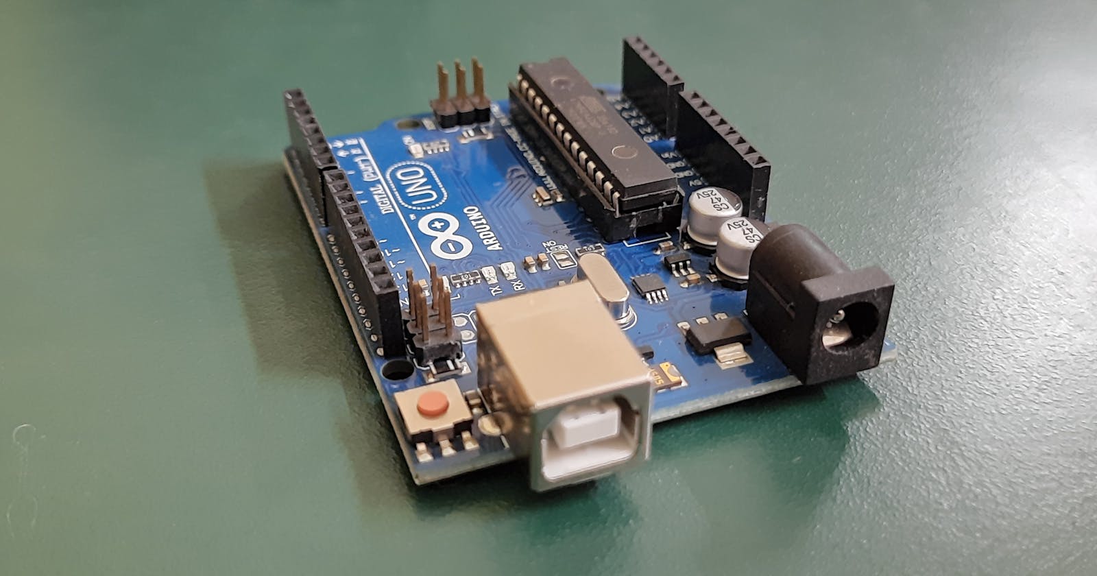
- Arduino UNO
- USB A to Type B Cable
- HC-SR04 Ultrasonic Sensor
- Active Buzzer
- Breadboard
- Jumper Wires
- 9V Battery
- LED (Optional)
I bought these above components from Robu.in. But you must compare the quality and price from different sites before purchasing the itmes.
2. The functionality of the Ultrasonic Sensor and Active Buzzer
Ultrasonic Sensor
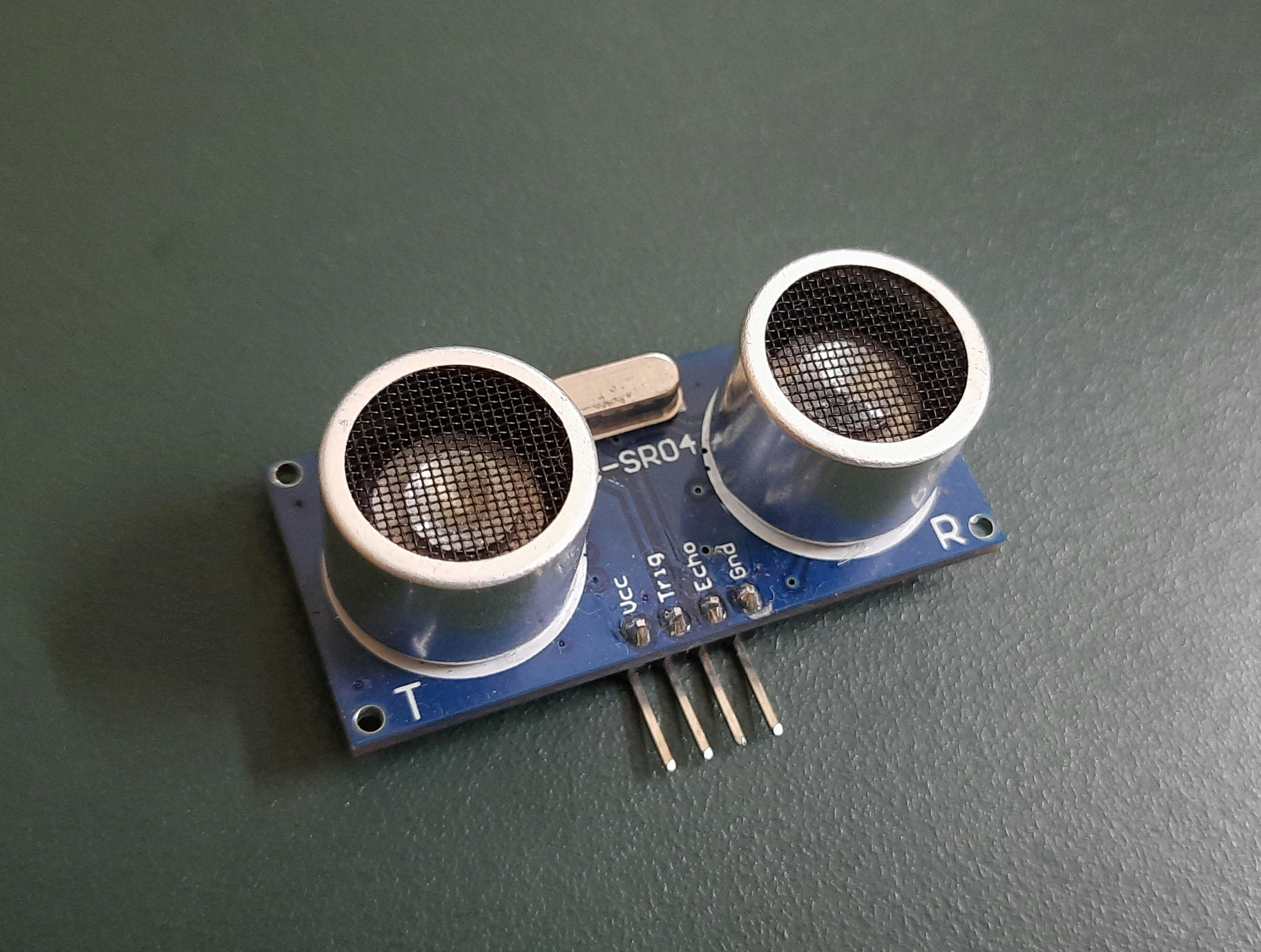
An HC-SR04 sensor or simply say an ultrasonic sensor is a type of distance sensor that can detect accurate distance at a range between 2cm to 400cm. There are four pins which are: Vcc, Trigger, Echo, and Ground. The first and the last pin are for 5V power supply and ground respectively. And the Trigger pin is for triggering ultrasonic sound pulses from the transmitter side and the Echo pin produces a pulse when it detects the reflected waves on the receiver side.
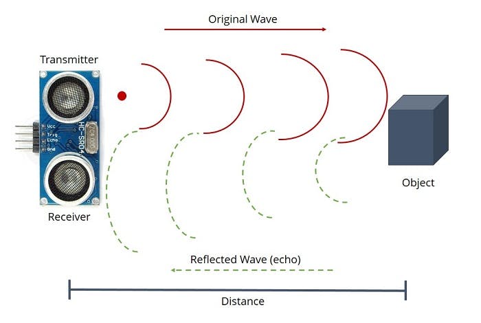
The distance is calculated using simple formulae which is ( Speed = Distance / Time ). Here, the sound speed of 340 m/s is considered and the time calculated by the echo pin is in microseconds (μS), so we need to convert it as 0.034 cm/μS.
Now, the overall formulae to get the distance (cm) will be:
$$
distance = (0.034 * time) / 2
$$
Divide by 2 because the distance traveled by the sound wave is twice the actual distance.
Active Buzzer
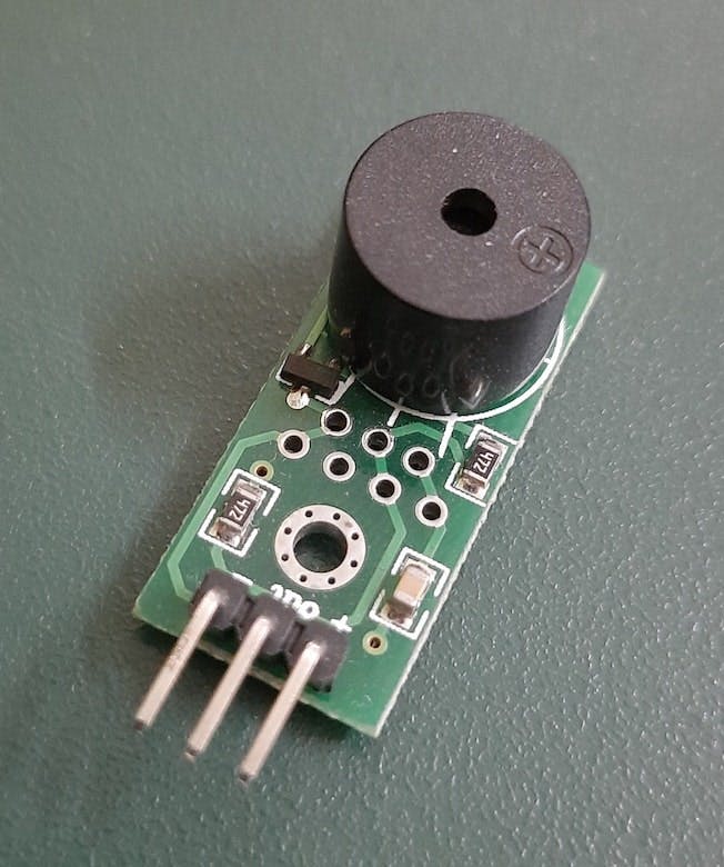 A 3 legged active buzzer works by an internal oscillator. The middle pin is for controlling the sound pitch by using a function tone() in Arduino IDE. This function helps us to produce different tones using frequencies in the range of 20Hz to 20kHz.
Active Buzzer means it uses DC signal as input while Passive buzzer means it uses AC signal as input.
3. Making the Circuit
You can use a breadboard for testing each component but making the final device will not require it because we can directly attach the pins to the sensor and buzzer. Here, the buzzer pin, trigger pin, and echo pin are connected to pin no. 8, 9, and 10 respectively of the Arduino board. While other pins to the 5V port, 3.3V port, and the Ground port.
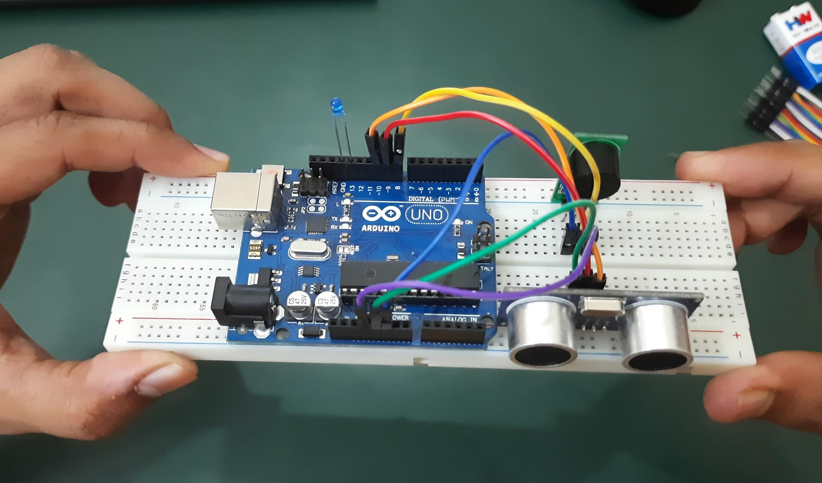
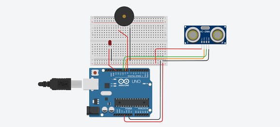
Here is the circuit sketch made using Tinkercad.
4. Making the Final device
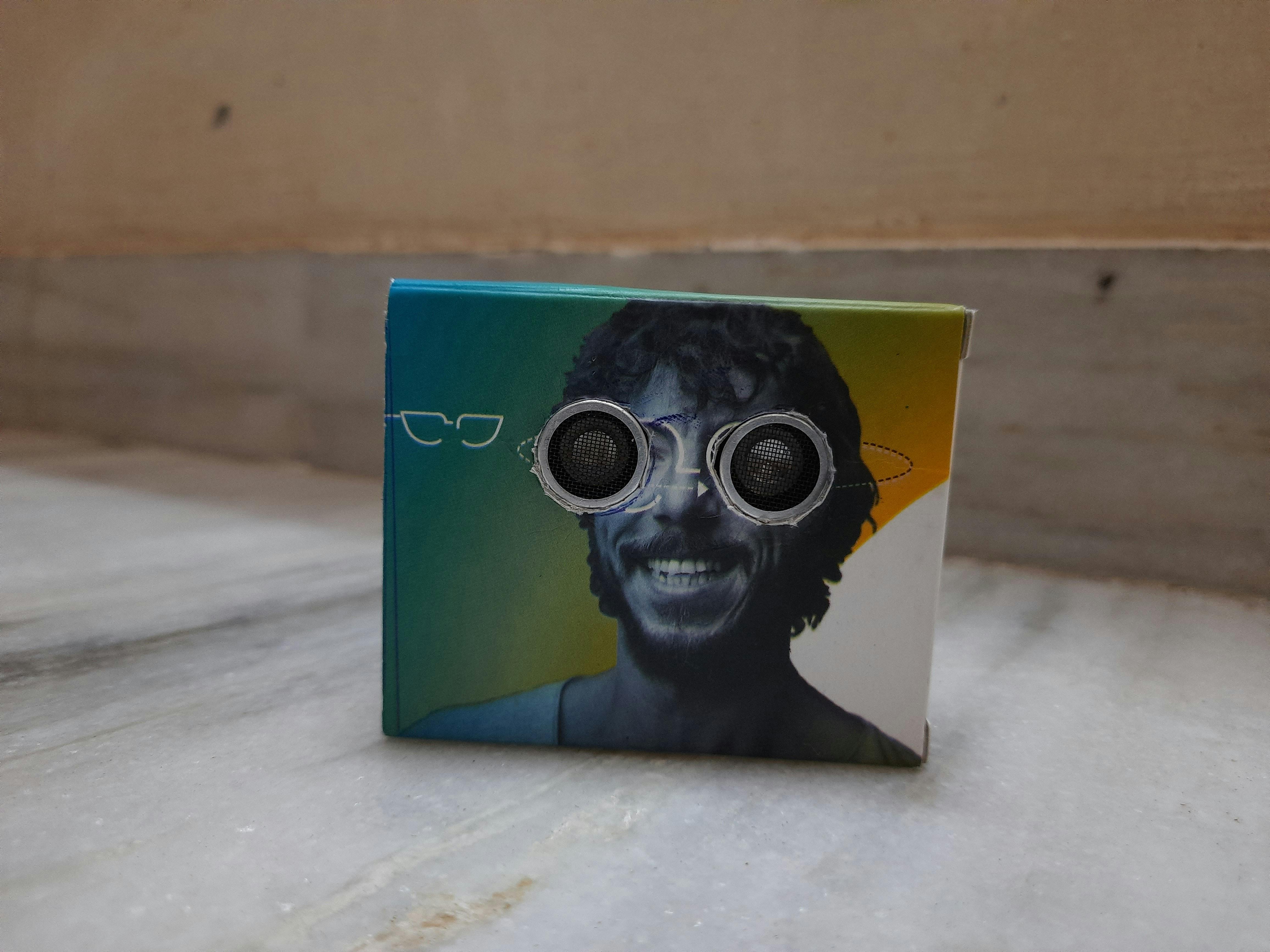
To accommodate the complete setup, I used a small box that is 8cm x 5cm x 7cm in dimension. I used the Lenskart box which was perfectly in size. But you can make your own through a cardboard box by getting all the actual measurements of the components that you are using. Make sure that, before attaching the setup inside the box, you have uploaded your final source code into the microcontroller.
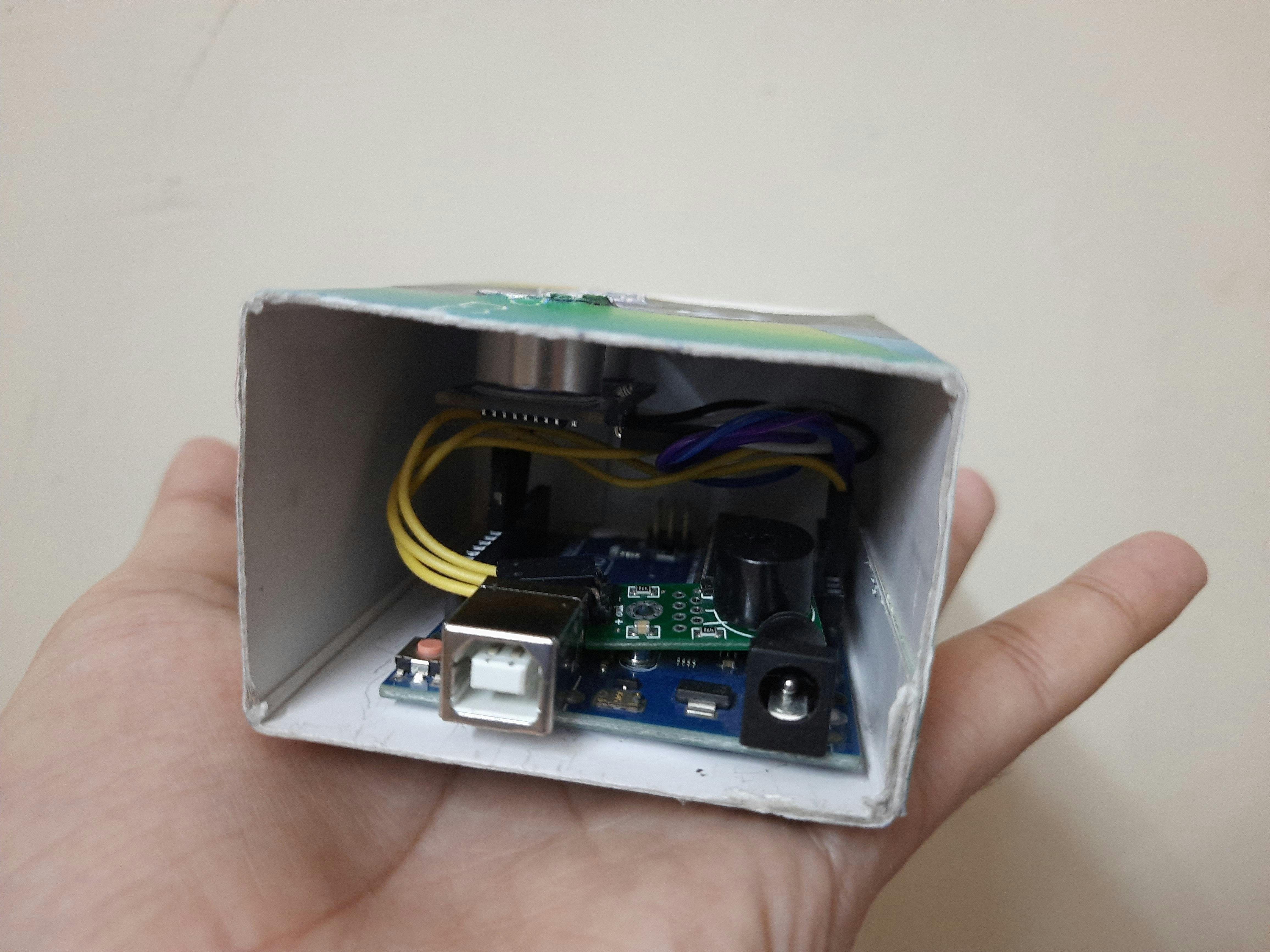
Now, make two holes in the center of the box whose diameter is equal to the diameter of the sensor's transmitter and receiver parts. Place the complete setup inside the box and place the sensor into those holes.
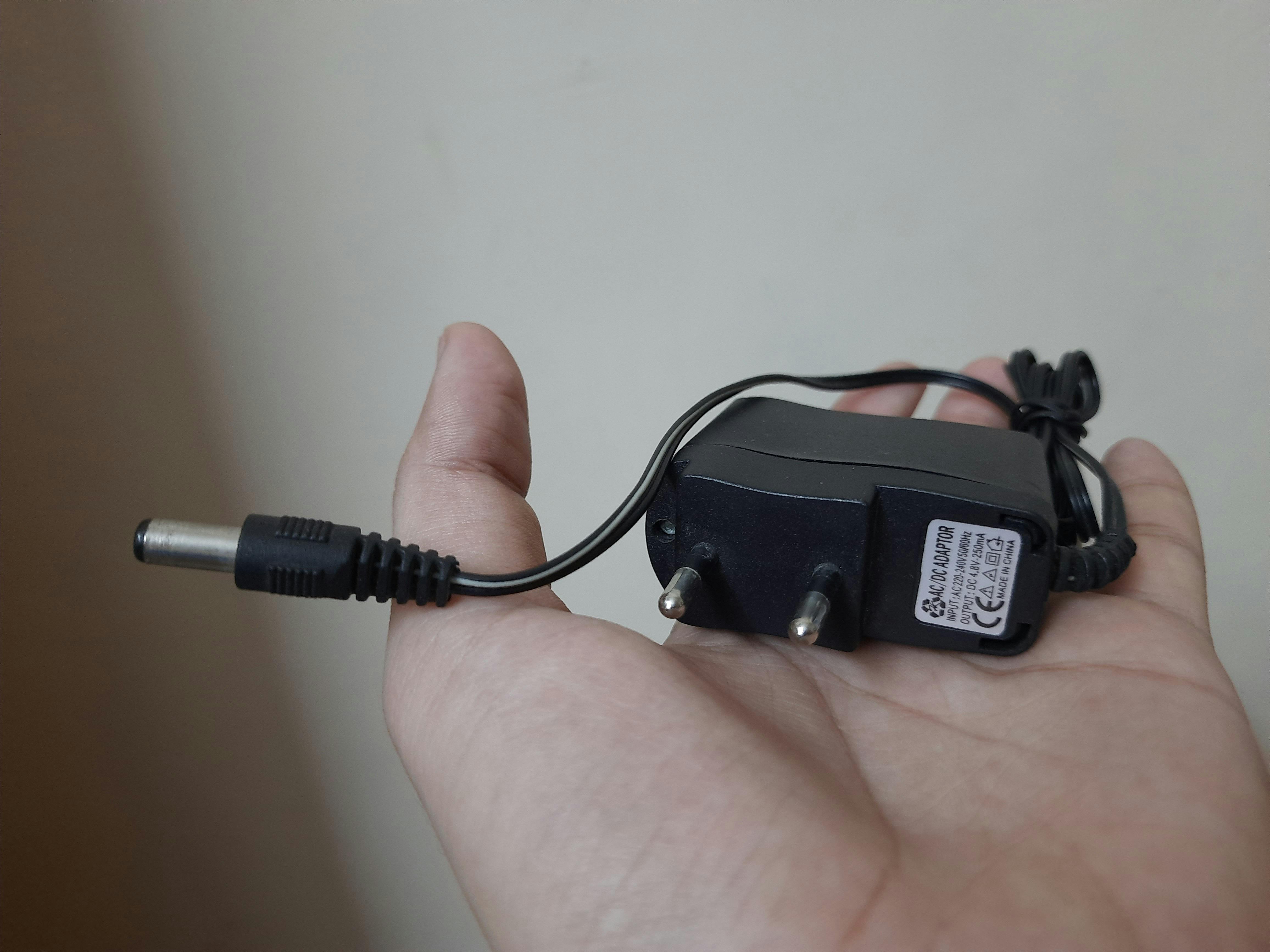
3. If you want to power the board using the 9V battery, then you need to use a DC power jack. But, I have used an adapter (which was already present while making the project) whose output rating is 4.8V.
5. Source code
To program the Arduino board, you need an Arduino IDE which you can download from here. But, you can also use an Arduino Web editor to program your board and can save your program sketch on the cloud.
6. Watch the video for a complete guide.
Note: For a better experience watch the video at 2x speed.